Starting System Wiring Diagram Basics
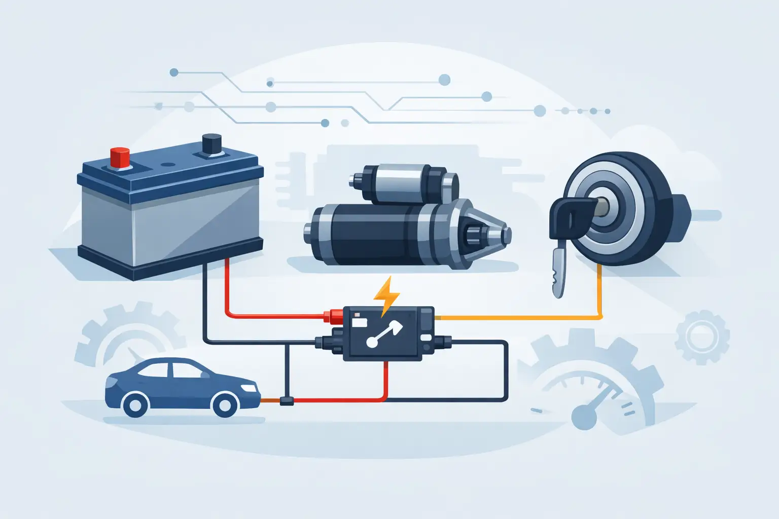
A no-crank vehicle can waste an hour fast if you start swapping parts before checking the circuit. A proper starting system wiring diagram cuts through that guesswork. It shows the power path, control side, grounds, connectors, fuse protection, and module involvement so you can test the system in the right order.
For technicians and advanced DIY owners, that matters because starting circuits are no longer just battery, switch, relay, and starter. On many late-model vehicles, the crank request may pass through a body control module, engine control module, transmission range switch, clutch switch, theft deterrent system, or a smart junction box. If you do not have the actual wiring layout for the vehicle in front of you, you can lose time chasing a problem in the wrong part of the circuit.
What a starting system wiring diagram actually shows
At a basic level, the diagram maps how battery voltage gets from the positive terminal to the starter motor and solenoid, and how the control side tells the starter when to engage. It also shows the return path through ground. That sounds simple, but the value is in the details.
A good diagram identifies fuse and fusible link locations, relay terminals, connector views, wire colors, splice points, ground references, and the modules tied into the start request. On older vehicles, the path may be short and direct. On newer platforms, the start command can move through multiple electronic decision points before the starter relay ever closes.
This is where exact vehicle data matters. A Ford truck, a Toyota sedan, and a BMW crossover can all have very different start authorization logic even if the symptom is the same. If the complaint is no crank, one system may need a clutch input, another may need park/neutral validation, and another may block cranking because of an immobilizer issue.
Reading a starting system wiring diagram without wasting time
The fastest way to use a starting system wiring diagram is to split the circuit into two sides: the high-current side and the control side. The high-current side usually includes battery power, maxi fuse or fusible link, starter relay load side, starter solenoid, and motor feed. The control side includes the ignition switch or push-button start logic, relay coil control, safety interlocks, and module commands.
Start at the component that fails to operate. If the starter does not engage, check whether the problem is lack of main feed, lack of command, poor ground, or an internal starter fault. The diagram tells you where each test should happen and what has to be present for the next step to work.
For example, if battery voltage is present at the starter B+ terminal but the solenoid trigger wire never gets power during crank, the diagram moves your attention upstream. You can then check the relay output, relay coil command, ignition switch input, and any park/neutral or clutch switch in the chain. If the trigger wire does get power but the starter does not respond, your testing shifts back to the starter assembly, cable voltage drop, or ground side.
This is also why connector IDs and ground locations matter. A diagram that only shows a generic circuit is less useful than one that identifies connector numbers, pin locations, and ground points by reference. Real repair work depends on that level of detail.
Common starting circuit layouts
Most starting systems fall into one of three broad layouts. The first is the traditional hard-wired design, where the ignition switch sends power directly through a neutral safety or clutch switch to a starter relay or solenoid. This is common on older vehicles and some base-model applications.
The second is a relay-controlled design where the ignition switch requests crank, but a module handles part of the decision-making. The relay may be grounded or powered by the PCM, BCM, or another controller after certain conditions are confirmed.
The third is a networked start system, common on push-button vehicles. In these systems, a start button is only the beginning of the request. Modules communicate over the network, verify key presence, brake pedal input, gear selection, and theft status, then command the starter relay. If you are diagnosing one of these systems with only a generic mental model, you will miss the logic path.
That difference changes the repair plan. On a simple circuit, a test light and meter may take you straight to the fault. On a network-controlled system, you may also need scan data to confirm crank request status, immobilizer approval, and relay command.
Why generic diagrams often create bad repairs
A generic starting diagram is fine for explaining principles. It is not fine for vehicle-specific diagnostics. Wire colors vary. Fuse names vary. Relay locations vary. Module strategies vary. Even within the same manufacturer, a 2014 model can be wired differently than a 2016 model with the same engine.
That is where many bad repairs start. A tech assumes terminal 85 is always ground-controlled, or that the crank fuse feeds the switch directly, or that the transmission range switch is inline when the vehicle actually reports gear position to a module digitally. The result is unnecessary relay replacement, starter replacement, or ignition switch replacement.
Accurate diagrams reduce those mistakes because they show the actual circuit used on the vehicle. They also help with intermittent faults, which are often harder than hard failures. If a vehicle cranks only sometimes, the diagram gives you the exact path to load-test connections, inspect splice points, and monitor the command side under the right conditions.
What to check on a no-crank diagnosis
A starting system fault is rarely solved by checking one point. You need the diagram, then you need a test sequence that matches it. In most cases, begin by verifying battery state of charge and cable condition. Low system voltage can distort the rest of the diagnosis.
After that, confirm whether the starter has constant battery feed. Then check whether the solenoid receives a crank signal during the key start or push-button request. If it does not, move back through the relay, ignition input, interlock switches, and module logic. If it does, evaluate voltage drop on the positive side and ground side before condemning the starter.
The trade-off is simple. If you skip ahead and replace the starter first, you might get lucky on an older system. On many newer vehicles, you will not. A start inhibit from the anti-theft system or a missing park input will leave the replacement starter doing nothing, and the vehicle comes back.
Diagram details that save the most time
Not every line on the page carries equal value during diagnosis. The details that usually save the most time are connector pinouts, splice references, fuse and relay identification, and ground locations. Wire color codes are useful, but only when they are paired with cavity numbers and connector names.
Module-controlled systems add another layer. If the diagram shows the BCM grounding the starter relay coil, you know a missing ground command can be caused by logic, input failure, wiring damage, or module fault. If the diagram shows the PCM receiving the crank request but the BCM controlling the relay, your scan approach changes. You need to know which module sees the request and which module executes it.
This is one reason shop productivity depends on documentation quality. Good electrical data shortens the gap between symptom and proof. It lets you test with purpose instead of probing random points under the dash.
Getting the right starting system wiring diagram
The best diagram is the one that matches the exact year, make, model, engine, and system configuration. That sounds obvious, but trim level, transmission type, keyless entry package, and market variations can change the starting circuit enough to matter.
If you are sourcing repair information, look for documentation that is built for system-level diagnosis rather than broad consumer reading. You want wiring paths, terminal IDs, connector callouts, and circuit protection details, not just a simplified picture. For shops and mobile technicians, instant digital access is usually the practical choice because the job is already in the bay and the answer is needed now.
AutoCarData fits that use case by giving buyers a direct way to get downloadable wiring and repair documentation for a wide range of vehicle brands without waiting on a full manual set or chasing scattered sources.
When the diagram is only part of the answer
A wiring diagram is critical, but it is not the whole job. You still need to verify the complaint, test under load, and understand how the vehicle is supposed to behave. A diagram will tell you where the path goes. It will not tell you whether a corroded cable passes current under starter load, or whether a module is withholding crank because of a live theft event.
That is why the best diagnostic flow pairs the diagram with voltage drop testing, scan tool data, and basic mechanical awareness. A seized engine, damaged flexplate, or failed starter drive can look electrical at first glance. The diagram helps rule the circuit in or out quickly.
When a no-crank problem lands in front of you, speed comes from accurate information, not faster guessing. Get the right starting circuit data first, and the rest of the repair gets a lot more predictable.