Charging System Wiring Diagram Basics
A no-charge comeback usually starts the same way – battery light on, low voltage at idle, and a parts cannon aimed straight at the alternator. That is exactly where a charging system wiring diagram saves time. When you can see the full path from battery to alternator, fuse block, PCM, regulator, and ground, you stop guessing and start testing.
Most charging faults are not caused by the alternator itself. They come from blown fusible links, corroded battery sense circuits, failed ignition feeds, weak engine grounds, or control-side problems that a meter alone will not explain without the schematic in front of you. If the vehicle uses smart charging, LIN communication, or PCM-controlled regulation, the diagram is not optional.
What a charging system wiring diagram actually shows
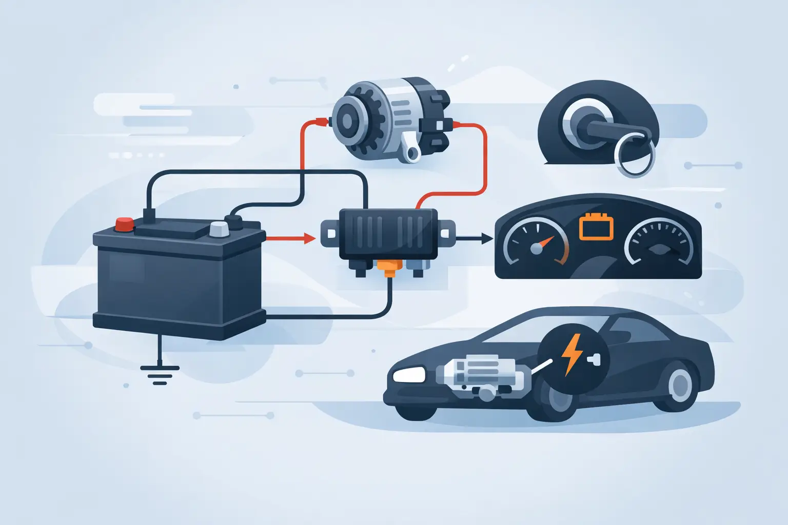
A proper charging system wiring diagram maps the entire circuit, not just the alternator connector. That includes the battery positive cable, mega fuse or fusible link, ignition feed, charge warning lamp or cluster circuit, current sensor if equipped, PCM or BCM involvement, and all related grounds.
On older systems, the layout is usually simple. You will see a battery output terminal, a field or regulator connection, and a lamp or ignition terminal. On newer vehicles, the alternator may have a multi-pin connector with duty-cycle control, voltage sense input, network communication, or load request feedback. The difference matters because test strategy changes with system design.
A good diagram also gives you wire colors, connector IDs, splice locations, ground points, and fuse references. That is what turns a voltage reading into a decision. Twelve volts missing at a control terminal means very different things depending on whether that terminal is fed by an ignition fuse, commanded by a module, or pulled low through the cluster.
Why generic charging diagrams waste shop time
A universal alternator diagram is fine for classroom basics. It is not enough for a 2016 Ford with smart charge, a late-model Toyota with ECM-managed output, or a European platform that routes charging control through multiple modules. Even within one manufacturer, charging circuits can change by engine, trim level, emissions package, or production date.
That is why make-specific and model-specific documentation matters. If the pinout is wrong, every voltage check after that is suspect. If the fuse location or splice reference is generic, you lose time opening the wrong panel or chasing the wrong harness branch.
For working techs and serious DIY owners, speed comes from accuracy. Buy and download the exact diagram set for the vehicle on the lift, and the diagnosis usually gets shorter fast.
Reading the charging system wiring diagram in the right order
The fastest way to use the diagram is to follow current flow, then follow control. Start at the battery and B+ output path. Confirm the alternator output stud has a direct path to the battery through the correct fuse or fusible link. If that path is open, a good alternator still will not charge the battery.
Next, identify the alternator connector terminals. One may be ignition feed, one may be sense, and one may be command or feedback. On some systems, the regulator is internal and mostly self-contained. On others, the PCM decides target voltage based on battery temperature, load, and operating conditions.
Then look at grounds. Charging complaints often come down to voltage drop on the engine block ground strap or corrosion at the battery negative connection. A diagram shows whether the alternator case is the only ground path or whether a dedicated ground circuit is involved.
After that, trace the indicator circuit. If the charge lamp circuit is part of regulator excitation, a cluster issue can create a no-charge condition. On newer systems, the warning lamp may be a module-driven message rather than a direct alternator circuit, so you need the actual schematic before calling the alternator bad.
Common circuit sections to verify first
In most no-charge or overcharge cases, the first checks are simple once the diagram is open. Verify battery voltage at the output stud, fuse continuity in the main charge path, ignition voltage at the correct terminal, and ground integrity under load. If the system is computer-controlled, confirm command and feedback circuits match the wiring layout before replacing parts.
This is also where connector views help. Backprobing the wrong cavity because a pinout was assumed instead of confirmed is an easy way to lose an hour.
Smart charging systems change the diagnosis
Many late-model vehicles do not regulate charging the old way. The PCM or another control module may reduce alternator output during acceleration, raise voltage during decel, or vary charge rate to support fuel economy strategy. That means a reading of 12.6 to 13.1 volts at idle is not always a fault by itself.
The diagram tells you whether the alternator is supposed to receive a PWM command, LIN bus signal, or a simple switched feed. Without that information, technicians often condemn a good alternator because expected behavior looks different from older systems.
There is a trade-off here. Smart charging improves efficiency and battery management, but it adds failure points outside the alternator. A damaged current sensor, an open battery sense line, or a network fault can create charging symptoms that basic alternator bench testing will miss.
Using the diagram with meter tests
A wiring diagram is not a replacement for testing. It is what makes testing mean something. Voltage checks, continuity checks, loaded voltage drop tests, and scan data all become more useful when tied to the actual circuit path.
If battery voltage is low and the alternator output terminal shows proper voltage, the diagram pushes you toward the charge cable, mega fuse, or connection issue. If the output stud is low and the field control circuit is missing, the fault is likely upstream. If command is present but output is unstable, then the alternator becomes a stronger suspect.
This is where exact circuit naming helps. Some manufacturers label the same function as GENCOM, FR, C, L, IG, or S. The wire function matters more than the label, and the diagram gives you that context.
What to look for in a professional charging system diagram
Not all diagrams are equally useful in the bay. The best ones show connector faces, ground locations, splice IDs, fuse and relay references, and clear routing between modules. You want enough detail to move from symptom to pinpoint test without opening three separate books.
Coverage across multiple brands matters too if your shop sees everything from Chevrolet and Ford to Honda, BMW, and Volvo. Charging systems are one of those categories where platform differences show up quickly, especially on hybrids, diesel applications, and European models.
If you are buying documentation, look for immediate digital access and vehicle-specific coverage rather than broad manual bundles you have to sort through. AutoCarData is built around that kind of direct access – buy and download the exact repair documentation you need, then start the diagnosis without waiting.
When the diagram prevents the wrong repair
A weak charging complaint can be battery condition, cable resistance, current sensor error, poor ground, PCM strategy, or an actual alternator failure. The wrong diagram, or no diagram, turns all of those into guesswork. That usually means extra parts, extra labor, and a vehicle that comes back.
The wiring schematic also protects you from overdiagnosing. If the vehicle is intentionally reducing output under certain loads and temperatures, replacing the alternator will not change normal operation. If the battery lamp is driven by the cluster based on network data, unplugging the alternator may not prove what you think it proves.
Exact wiring information keeps the repair narrow. It tells you what is in the circuit, what is not, and where to test next.
Charging system wiring diagram mistakes to avoid
The most common mistake is assuming all three-wire or four-wire alternators work the same way. They do not. Another is checking charging voltage only at the battery and skipping the alternator output stud and ground side voltage drop. A third is ignoring fuseable links because they look fine visually.
There is also the habit of replacing the battery and alternator together before verifying control circuits. On older vehicles that may work often enough to seem efficient. On newer systems, it gets expensive fast.
A clean diagnosis starts with the right diagram, then follows the circuit one section at a time. That approach is slower for the first five minutes and faster for the next ninety.
When a charging issue lands in your bay, the best move is simple – get the exact wiring diagram for that vehicle, verify the power path, verify the control path, and let the circuit tell you what failed.