Volkswagen Wiring Pinout Reading for Fast Repairs

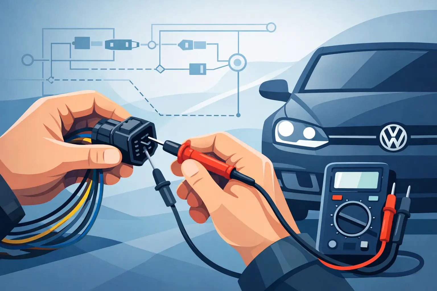
A Volkswagen wiring pinout is only useful when it matches the vehicle in front of you. A connector that looks identical across Golf, Jetta, Passat, Tiguan, or Atlas models can carry different circuits based on model year, engine, transmission, trim level, market, and installed options. Before probing a terminal, confirm the exact vehicle configuration and the connector designation shown in the wiring documentation.
For electrical diagnosis, a pinout does more than identify wire positions. It tells you what each terminal is supposed to do, where the circuit originates, where it goes next, and what conditions must exist for the circuit to operate. That is the difference between finding a failed power feed and replacing a module that was never the problem.
What a Volkswagen Wiring Pinout Shows
A pinout is a terminal map for a connector, control module, sensor, actuator, fuse panel, relay carrier, or harness junction. It identifies the connector housing, terminal numbers, wire colors, circuit functions, and often the wire size. In Volkswagen documentation, the pinout normally works alongside a current flow diagram rather than replacing it.
The connector view answers a physical question: which cavity is terminal 1, terminal 20, or terminal 73? The current flow diagram answers an electrical question: what feeds that terminal, what it controls, and what components share the circuit? Use both. A terminal number without circuit context can lead to a false diagnosis.
Volkswagen wiring diagrams commonly identify components with letter-and-number references. For example, a control module, switch, sensor, or connector may be assigned a specific designation that appears throughout the diagram set. Follow that designation instead of relying on component location alone. On vehicles with multiple similar connectors, especially around the engine bay, dash harness, and door modules, connector position can vary with options and production changes.
Start With Vehicle Identification, Not Wire Color
Wire color is a helpful confirmation, but it is not a reliable starting point. Volkswagen harnesses can use the same base color for several circuits, and stripe colors may fade, become obscured by dirt, or look different under poor lighting. Previous repairs can also introduce non-factory wire, incorrect splices, or replacement connector pigtails with mismatched colors.
Start by recording the VIN, model year, engine code, transmission type, and relevant equipment. For Volkswagen vehicles, option codes can matter as much as the trim badge. A vehicle with a premium sound system, adaptive cruise control, parking assist, heated seats, start-stop, or all-wheel drive may have additional modules and different harness branches.
Then identify the part you are testing by its documented designation and connector number. Verify the connector keying, cavity count, and locking-tab orientation before counting pins. Many connector views are shown from the terminal side, while you may be looking at the wire side on the vehicle. If the documentation does not clearly state the viewing direction, compare the connector shape and locator features before inserting a test lead.
Reading Volkswagen Wiring Pinout Information Correctly
Volkswagen diagrams use conventions that can save time once you understand them. Terminal designations are especially useful because they describe circuit purpose across many systems. Terminal 30 is typically unswitched battery positive. Terminal 15 is ignition-switched positive. Terminal 31 is ground. Terminal 50 is the starter control circuit. These conventions are valuable, but they do not eliminate the need to verify voltage under the actual operating condition.
A terminal listed as power supply may not show battery voltage at all times. It may be switched by a relay, activated by a control module, protected by a fuse, or available only when the vehicle is awake. On late-model Volkswagen platforms, modules can remain active briefly after key-off, enter sleep mode, or wake through network activity. Testing at the wrong time can make a normal circuit appear faulty.
Pay close attention to these pinout details:
- Connector designation and number of cavities
- Pin number and connector-view orientation
- Wire color and wire gauge
- Fuse, relay, splice, or junction location
- Ground point designation
- Circuit destination and control module involvement
- Signal type, such as analog voltage, LIN, CAN, PWM, or switched ground
The signal type determines the correct test method. A basic test light can be useful on a high-current lamp or relay circuit, but it can damage or load sensitive low-current circuits. Do not use one on CAN, LIN, sensor reference, airbag, or module communication terminals. Use a digital multimeter with appropriate back-probes, and use a lab scope when checking communication lines, pulse-width-modulated outputs, or intermittent sensor signals.
Pin Numbers Are Not Always Circuit Numbers
A frequent mistake is treating a pin number as if it identifies a circuit across every Volkswagen model. Pin 4 on one engine control module may be a sensor ground, while pin 4 on another version of the same module housing may serve an entirely different function. Software revisions, engine variants, and module part numbers can change assignments.
Match the documentation to the module part number when possible. If a replacement module, used harness, or aftermarket component is involved, confirm whether its connector assignment is compatible before powering the circuit. Physical fit does not prove electrical compatibility.
Trace the Circuit Before Replacing a Part
A correct pinout gives you a test path. Begin at the symptom, then trace backward or forward through the circuit. If a fuel injector, cooling fan, window motor, or sensor is not operating, do not jump directly to the component. Check whether the load has power, ground, command, and a complete path under load.
For a two-wire sensor, you may be checking a reference voltage and sensor ground. For a three-wire sensor, there may be a reference, ground, and return signal. For a module-controlled actuator, one side may have constant or switched power while the control module completes the ground path. The pinout and current flow diagram reveal which arrangement applies.
Voltage readings alone can be misleading. A terminal can show 12 volts with no load and still fail when the circuit is asked to carry current. If the circuit is appropriate for load testing, check voltage drop across the power and ground sides while the component is commanded on. Excessive drop points to corrosion, damaged wire, a weak connection, or a failing relay contact.
Grounds deserve the same attention as power feeds. Volkswagen ground points can serve multiple systems, and a loose or corroded ground may create unrelated fault codes across lighting, comfort, engine, and network systems. The wiring pinout identifies the ground circuit, but the full diagram helps locate shared splices and chassis ground points.
Common Volkswagen Connector Testing Errors
The fastest diagnosis is often lost through avoidable connector damage. Do not force oversized probes into small terminals. Terminal tension can be weakened, creating an intermittent fault after the repair attempt. Use proper back-probes or breakout leads whenever possible, and inspect the connector for spread terminals, moisture intrusion, corrosion, and poor terminal retention.
Avoid piercing insulation unless there is no practical alternative. Pierced wires can corrode internally, particularly in engine compartments, wheel-well harnesses, and areas exposed to road spray. If a wire must be pierced for a test, seal the repair correctly afterward.
Also verify fuses with the circuit loaded or commanded on. A visual fuse check is not enough. A fuse can appear intact while a poor fuse-box connection, overheated terminal, or upstream supply issue prevents current flow. The pinout tells you where power should arrive; a voltage-drop test tells you whether the circuit can actually deliver it.
When You Need the Full Wiring Diagram Set
A standalone pinout can solve a simple connector identification problem. It is not enough for complex faults involving multiple modules, shared power supplies, network communication, intermittent no-start conditions, or option-dependent systems. For those repairs, you need the complete wiring path, including fuse assignments, relay logic, ground distribution, splice locations, connector locations, and component views.
This matters on Volkswagen vehicles because many systems are controlled through modules rather than direct switch-to-load wiring. A window problem may involve the door control module, central electrics, comfort network, fuse supply, and the motor assembly. A no-communication fault may start with a damaged CAN wire, but it can also result from a low-voltage module, water intrusion, a shorted component, or a missing power or ground feed.
Accurate downloadable wiring documentation lets you pull the correct diagrams before opening the harness or ordering parts. AutoCarData provides repair-focused technical documentation for technicians and advanced vehicle owners who need exact system information without waiting on a printed manual.
A pinout should direct your test, not replace it. Confirm the vehicle configuration, identify the connector from the correct viewing side, test the circuit under the conditions where it fails, and follow the diagram until the fault is proven. That approach protects modules, reduces unnecessary parts replacement, and gets the Volkswagen repair moving in the right direction.