Module Communication Fault Example and Diagnosis

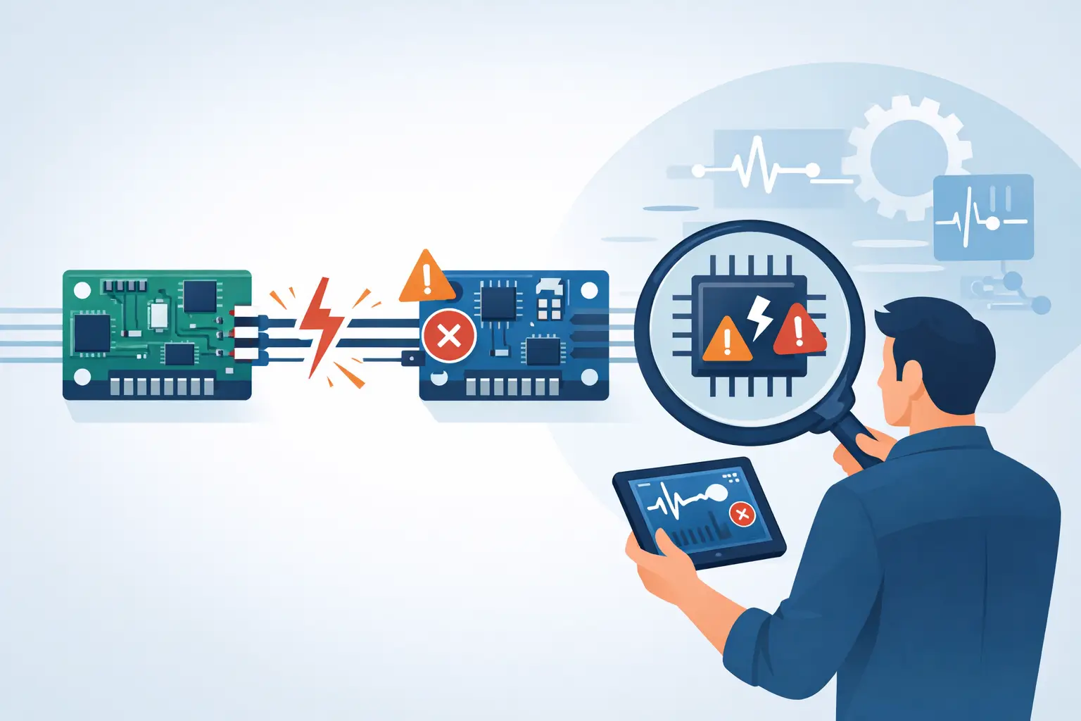
A module communication fault example usually starts with a vehicle that still runs, but several systems stop working at once. The scan tool may show multiple U-codes, the dash may light up with unrelated warnings, and one controller may not appear in a full vehicle scan. That does not automatically mean the missing module has failed. It means the network needs to be tested before parts are ordered.
For technicians and advanced DIY owners, the fastest path is to identify which module is missing, determine which network it uses, and verify the basics: battery voltage, ignition feed, ground, and network integrity. A correct wiring diagram is what turns a list of U-codes into a repair plan.
What a Module Communication Fault Means
Modern vehicles use multiple control modules that exchange data over networks such as CAN, CAN FD, LIN, FlexRay, or manufacturer-specific communication buses. The engine control module, transmission controller, ABS module, body control module, instrument cluster, steering module, and infotainment unit all depend on that data.
A communication DTC is commonly a U-code. For example, U0100 often indicates lost communication with the engine control module, while U0121 commonly points to lost communication with the ABS or brake control module. The exact code definition can vary by manufacturer, so the code description and circuit information for the specific vehicle matter.
The key distinction is between a module that cannot communicate and a module that is actually defective. A dead module is one possible cause. A blown fuse, weak ground, water intrusion, corroded connector, damaged CAN wires, or low system voltage can create the same scan result.
Module Communication Fault Example: U0121 on a CAN Network
Consider a vehicle with an ABS warning light, traction control warning, power steering warning, and several stored U0121 codes. The engine starts normally, but the scan tool cannot communicate with the ABS control module.
Other modules may store U0121 because they expect wheel speed, brake status, and vehicle speed data from the ABS module. The power steering module may set a communication code because it no longer receives vehicle speed information. The instrument cluster may show warnings because it is missing messages from both systems. These are often secondary codes, not separate failures.
The initial suspicion may be a failed ABS module. Before replacing it, verify the failure path:
- Check battery voltage and charging voltage. Low voltage can cause modules to reset or drop off the network.
- Check the ABS module fuses with a loaded test, not only a visual inspection. A fuse can look intact but fail under load because of corrosion or a poor terminal connection.
- Verify constant battery power, ignition-switched power, and ground at the ABS module connector.
- Inspect the harness near the wheel well, frame rail, battery tray, and underhood fuse block. These areas are common damage points.
- Test the CAN circuits at the module and at the diagnostic connector.
If power and ground are correct but the network remains shorted or open, the issue is in the communication circuit or another module on that bus. If the network tests correctly and the ABS module will not communicate while all its feeds are present, module replacement becomes a more reasonable next step.
Read the Full Scan Before Disconnecting Anything
A full vehicle scan provides the direction for network diagnosis. Record all codes, module status, and scan tool communication results before clearing anything. Pay close attention to which modules report lost communication and which module cannot be accessed.
If every module communicates except one, focus on that module’s power, ground, connector, and local CAN branch. If several modules on the same network are offline, look for a shared fuse, splice, network junction, gateway module, or damaged trunk line.
Gateway modules need special attention. Many late-model vehicles use a body control module, central gateway, or telematics unit to route messages between high-speed and low-speed networks. A module may look offline from one network even though the actual fault is a gateway power supply, configuration issue, or bus-side short.
Do not assume every stored U-code is current. A low battery event, jump-start, previous repair, or disconnected connector can leave historical communication codes in memory. Check code status, freeze-frame information when available, and whether the fault returns immediately after clearing.
Test Power and Ground First
Controllers cannot communicate reliably without stable voltage and a low-resistance ground path. This is basic testing, but it prevents expensive misdiagnosis.
Use the vehicle-specific wiring diagram to identify every power and ground terminal at the affected module. Many controllers have more than one power source. One may keep memory alive, another may wake the module with the ignition on, and a third may feed internal drivers. Missing one feed can produce a no-communication condition even when another power terminal reads 12 volts.
Voltage-drop testing is more useful than an unloaded resistance check. With the circuit operating or a test load applied, measure voltage drop from the module ground terminal to battery negative. Excessive voltage drop indicates resistance in the ground circuit, ground eyelet, connector, or splice.
Do the same for the power side when necessary. A terminal can show battery voltage with the connector unplugged, then fall below operating voltage when the module is connected. Loose fuse terminals, corroded relay contacts, and damaged wiring can cause this condition.
Check CAN Bus Integrity Without Guessing
Most high-speed CAN networks use two twisted wires: CAN High and CAN Low. Twisting helps the pair reject electrical interference. The wiring diagram will show wire colors, splice locations, connector views, and whether the affected module is on high-speed, low-speed, or another network.
With the vehicle powered down and the network allowed to sleep, a resistance check between CAN High and CAN Low at the diagnostic connector often reads about 60 ohms on a properly terminated two-resistor high-speed CAN bus. A reading near 120 ohms may indicate one missing termination or an open in part of the network. A very low reading can suggest a shorted module or wiring. A reading that changes significantly as modules are disconnected can help isolate the faulty branch.
This check is useful, not absolute. Some vehicles use gateways, sleep strategies, multiple buses, or network designs that affect what you read at the diagnostic connector. Follow the manufacturer-specific test procedure when available.
A scope is the best tool for confirming live CAN activity. A healthy signal pattern is more meaningful than a static voltage number, especially when intermittent faults occur. However, a scope pattern alone does not prove every module is healthy. It only shows that network traffic is present at the point tested.
Isolate the Fault Carefully
When a bus is shorted, disconnecting modules one at a time can identify the source. This should be controlled, not random. Start with the modules on the affected network, using the wiring diagram to locate branches and connectors. After each disconnection, recheck network resistance or scan tool communication.
Be aware of the trade-off: disconnecting modules can set additional codes and may require relearns, calibrations, or window and steering angle initialization on some vehicles. Keep the battery supported and document what was disconnected.
Water damage deserves close inspection. A module may be internally shorted after water enters a connector, but the root cause can be a leaking windshield, blocked sunroof drain, damaged cowl seal, or flooded floor harness. Replacing the controller without correcting the water path can repeat the failure.
Confirm the Repair Before Releasing the Vehicle
After repairing wiring, restoring a power feed, cleaning a connector, or replacing a module, perform a full scan again. Confirm the previously missing module communicates, clear codes, cycle the ignition, and verify which codes return.
Then test the systems that depended on the missing data. In the U0121 example, that may include ABS operation, traction control status, vehicle speed data, steering assist warnings, and instrument cluster messages. If module programming or configuration was required, confirm the replacement module has the correct software and option coding.
A communication fault is rarely solved by code description alone. Get the correct wiring diagram, identify the exact network path, and test the circuit in order. That approach protects repair time, avoids unnecessary module replacement, and gives the vehicle a repair that lasts.