How to Identify Chassis Components Fast

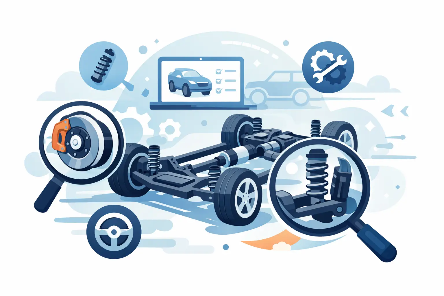
If a vehicle comes in with a pull, clunk, uneven tire wear, or vague steering, the fastest way to waste time is guessing what you are looking at. Knowing how to identify chassis components correctly is what separates a quick diagnosis from a parts-swapping job that keeps coming back.
For most technicians and advanced DIY owners, the challenge is not recognizing a control arm or a strut in general. The real problem is identifying the exact component layout on the vehicle in front of you, especially when platforms vary by trim, drivetrain, suspension package, or production date. A front suspension on one model year can look familiar enough to fool you and different enough to cause a wrong call.
How to identify chassis components without guessing
Start with the system, not the part. Chassis components are easier to identify when you group them by function: suspension, steering, braking support hardware, frame or subframe structure, and wheel-end assemblies. Once you know which system is responsible for the symptom, the parts around that system become easier to separate visually.
If the complaint is a steering bind, focus first on the rack, tie rods, knuckles, steering column linkage, and mounting points. If the issue is ride height, impact harshness, or tire cupping, move toward the springs, dampers, control arms, bushings, stabilizer links, and related mounts. This sounds basic, but it prevents a common mistake – identifying components by shape alone instead of by role in the assembly.
On most vehicles, the easiest anchor points are the knuckle, subframe, and shock or strut tower. From those fixed references, you can trace what connects where. A lower control arm usually runs from the subframe to the knuckle. A tie rod runs from the steering gear to the knuckle. A stabilizer link connects the anti-roll bar to a strut or control arm, depending on design. Following connection points is more reliable than relying on memory.
Start with the major chassis assemblies
Before getting into small hardware, identify the large assemblies first. The front and rear suspension architecture tells you what smaller components you should expect to see.
A MacPherson strut front end is usually straightforward. You will typically see a strut assembly that combines the damper and spring, one lower control arm per side, a steering knuckle, a tie rod end, and a stabilizer bar with links. A double-wishbone setup adds an upper control arm, which changes both part count and motion path. A multi-link rear suspension can add several lateral and trailing links that look similar at first glance, so documentation matters more there than on simpler layouts.
Solid rear axles are easier to read visually but still vary. One setup may use leaf springs, while another uses coil springs with trailing arms, track bar, and separate shocks. If you misidentify the locating member, you can misread the source of axle shift or rear steer.
This is why chassis identification always works better when you determine the suspension type first. Once you know the architecture, the part names become narrower and more accurate.
The core parts to recognize on sight
Most chassis inspections revolve around a repeat group of components. Control arms manage wheel movement through pivot points and bushings. Ball joints allow angular movement between suspension members and the knuckle. Tie rods transfer steering input. Struts and shocks control oscillation, while springs carry vehicle weight. Sway bars reduce body roll, and links connect them into the suspension.
Then there are the parts people overlook because they are not the obvious wear items. Subframes, crossmembers, radius arms, trailing arms, cam bolts, eccentric adjusters, cradle mounts, bump stops, and wheel bearings all affect chassis behavior. Some are structural, some are alignment-related, and some become the root cause of noise after collision work or previous repairs.
If two parts look similar, ask what they are mounted to and whether they pivot, support load, or transfer steering force. That usually clarifies what you are looking at faster than trying to remember terminology from another platform.
Use position and attachment points to identify parts
The fastest practical method is to identify each part by its location and attachment style. Chassis components almost always reveal their job through their mounting points.
A control arm usually has inboard pivots with bushings and an outboard ball joint or fixed connection at the knuckle. A trailing arm generally runs fore-aft and controls longitudinal wheel motion. A lateral link runs more side-to-side and helps control toe or camber depending on design. A sway bar is torsional and mounted to the body or subframe with brackets and bushings, then connected by links to moving suspension parts.
Struts and shocks are often confused by less experienced techs, but the mounting tells the story. A strut is usually structural in the suspension geometry and bolts directly between body and knuckle. A shock is only a damper and does not locate the wheel by itself. That difference matters when you are tracing wear patterns or determining what affects alignment angles.
At the wheel end, the steering knuckle is the hub carrier for multiple connections. It becomes a useful reference because tie rods, ball joints, struts, and hub assemblies all converge there. If you identify the knuckle first, the surrounding components become easier to label correctly.
How to identify chassis components on modern platforms
Newer vehicles make visual identification less straightforward. Covers, undertrays, active suspension hardware, ride height sensors, electronic dampers, and ADAS-related steering components can hide or complicate what used to be obvious. The old habit of taking one look from the side of the lift is often not enough.
That is where make-specific repair information saves time. A platform may have standard suspension on one trim, adaptive damping on another, and air suspension on a premium package. The mounting points can look familiar while the service procedure, torque specs, and component naming are different. Using the wrong diagram or generalizing from a similar model is where errors start.
For shops handling mixed makes, that problem shows up every day. European platforms may use multi-link layouts with several similar-looking arms. Trucks may have steering and suspension layouts that change with 2WD versus 4WD. Crossovers may share a body but use different rear suspension designs by engine or package. Exact chassis data matters because visual similarity is not the same as parts interchange or service equivalence.
Why documentation matters more than memory
Memory helps with common platforms, but it has limits. If you are diagnosing a single clunk on a vehicle you do not see often, exact diagrams beat assumptions every time. A proper chassis diagram shows component names, mounting positions, exploded views, and sometimes side-specific differences that are easy to miss under the vehicle.
This is especially useful when a part is hidden, partially obstructed, or referred to differently by aftermarket catalogs. What one source calls a tension strut, another may group under lower control arm variants. The vehicle does not care what the catalog called it. You still need to identify the correct component before inspection or replacement.
For that reason, many techs keep visual inspection and documentation side by side. Look at the vehicle, confirm the layout, then verify the exact component in the chassis data before ordering parts or quoting labor. If you need fast access to downloadable chassis information across multiple brands, that is where a source like AutoCarData fits the job.
Common mistakes when identifying chassis parts
The biggest mistake is assuming symmetry means sameness. Left and right may mirror each other, but front and rear links in a multi-link setup may look close enough to confuse, especially off the vehicle. Another mistake is identifying the failed part based only on where the noise seems to come from. Chassis noise travels.
It is also common to confuse mounts with moving members. A worn subframe bushing can feel like a control arm issue. A failed strut mount can sound like a sway bar link. A loose rack mount can mimic inner tie rod play. If you identify only the visible moving part and ignore the mounting structure, you can miss the actual fault.
Aftermarket modifications add another layer. Lift kits, lowering springs, adjustable arms, and non-OE sway bars can change what you expect to see. In those cases, start by identifying what is factory and what is not. Otherwise, you may spend time searching for a component that no longer matches stock configuration.
A simple workflow that speeds up identification
In the bay, the most efficient approach is consistent. Verify the complaint, isolate the affected end of the vehicle, identify the suspension type, anchor yourself with major components, and trace connections outward. Then confirm names and layout with vehicle-specific chassis documentation before teardown.
That workflow sounds simple because it is. The point is not to make chassis identification academic. The point is to cut down wasted motion, wrong parts, and repeat inspections. Whether you are dealing with a domestic truck, a Japanese sedan, or a European SUV, the process holds up because it is based on layout and function, not guesswork.
When you can identify chassis components quickly and accurately, every next step gets easier – inspection, measurement, ordering, quoting, and repair. Start with the system, verify the layout, and let the vehicle-specific data do the rest.