Brake Light Circuit Diagram Explained
A brake lamp problem rarely stays isolated for long. What starts as a simple “brake lights not working” complaint can turn into a failed inspection, a dead battery, a shift interlock issue, or a traction control warning if the signal is shared across modules. That is why a brake light circuit diagram matters – it shows exactly where power starts, where it is switched, which modules are involved, and where the circuit is grounded.
For a technician or serious DIYer, guessing is what wastes time. A proper wiring view lets you move straight to voltage checks, switch testing, connector inspection, and module input verification. If the fault is intermittent, the diagram is usually the difference between a quick repair and an hour of back-probing the wrong wire.
What a brake light circuit diagram actually shows
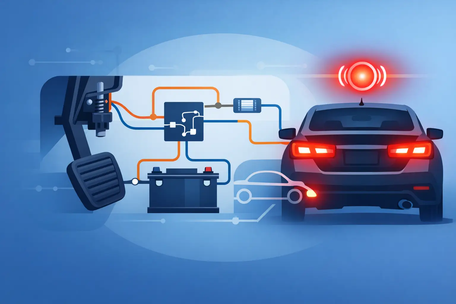
At the basic level, the circuit is simple. Battery voltage feeds a fuse, the brake pedal switch closes when the pedal is pressed, and power reaches the rear stop lamps. Ground completes the circuit, and the bulbs illuminate.
On many late-model vehicles, that basic path is only part of the story. The brake pedal switch may send a signal to the body control module, ABS module, transmission control system, cruise control circuit, and shift lock control. In some designs, the module does not just monitor the switch – it actually controls the brake lamp output. On others, the rear lamps are LED assemblies with internal electronics, which changes how voltage and current readings look during testing.
A usable diagram shows more than a line from point A to point B. It identifies fuse locations, splice points, connector IDs, wire colors, ground points, module pins, and whether the switch is normally open or normally closed. That detail is what allows a repair to be confirmed instead of assumed.
Reading a brake light circuit diagram without wasting time
The fastest way to read the diagram is to follow the circuit in order of operation. Start with the power source. Find the battery feed or ignition feed, then the fuse, then the brake switch, then any control module or relay, then the rear lamp assemblies, and finally the ground path.
That sounds obvious, but many brake light faults get misdiagnosed because the test starts at the bulb socket and never accounts for upstream control logic. If the circuit is module-controlled, lamp output may depend on switch input, ignition status, network communication, or internal module drivers. In that case, checking only for battery power at the socket may not tell you enough.
Pay attention to symbol differences. A mechanical brake switch is not the same as a pressure switch, and a module-controlled transistor output is not the same as a relay-switched output. The trade-off is straightforward: older circuits are easier to trace manually, while newer circuits provide more integration but add more failure points and more test steps.
Connector views also matter. Many diagrams tell you the connector number but not the physical location unless you have the full service information. If you are working on a make where rear body harness connectors are known to corrode or chafe near trunk hinges, slider doors, or trailer wiring splices, location data becomes as valuable as the circuit path itself.
Common brake light circuit layouts
There is no single layout that fits every vehicle. Still, most systems fall into a few patterns.
Simple switch-to-lamp circuit
This is common on older cars, basic trucks, trailers, and some fleet vehicles. Power runs through a fuse to the brake switch, then directly to the left and right stop lamps. Diagnosis is usually fast because there are fewer decision points. If both lights are out, you check fuse, switch input, switch output, and ground. If one side is out, you focus on the bulb, socket, wiring branch, or local ground.
Switch input to body control module
This is common on modern passenger vehicles. The brake switch sends a low-current signal to a body control module, which then energizes the stop lamps through internal drivers or an external relay. This setup supports features like bulb-out monitoring, cruise cancel logic, and integrated rear lighting control. The downside is that a bad switch signal, module fault, or communication issue can all mimic a wiring problem.
Shared stop and turn lamp circuit
Many trucks and older domestic vehicles use a combined stop-turn setup. In these systems, the brake lamp feed may route through the multifunction switch or turn signal switch. If one rear lamp flashes correctly but does not light during braking, the issue may be in the multifunction switch path rather than the rear lamp wiring itself.
LED brake lamp systems
LED assemblies reduce current draw and improve lamp life, but they can complicate testing. A conventional test light may not always load the circuit properly, and pulse-width modulation can make voltage readings look inconsistent. In these cases, the brake light circuit diagram is essential because it shows whether you are dealing with a direct feed, a controlled output, or a smart lamp assembly.
Using the diagram for real diagnosis
A diagram is only useful if it drives the next test. Start with the symptom and match it to the most likely failure path.
If both brake lights are out, check for battery voltage at the stop lamp fuse first. If the fuse is good and powered, move to the brake pedal switch. You want voltage into the switch and voltage out of the switch when the pedal is pressed. If input is present but output is not, the switch or its adjustment is likely the problem.
If the switch output is correct but the lamps stay off, the next step depends on circuit design. On a direct circuit, go downstream toward the rear harness. On a module-controlled circuit, verify that the module sees the brake switch input. A scan tool may show live data for brake switch status, which can save time before you ever touch the rear body wiring.
If only one lamp is out, compare the working side to the failed side. Same connector family, same expected voltage, same ground path style. Side-by-side comparison is often faster than decoding every branch from scratch.
If the lights stay on all the time, do not jump straight to the switch. A misadjusted pedal switch is common, but so is a stuck relay, shorted module output, bent pedal stopper, or aftermarket wiring issue. Trailer harness additions are repeat offenders here. They can backfeed the stop lamp circuit and create symptoms that look like a switch fault.
Why exact vehicle data matters
Brake lamp circuits vary more than many people expect. A Ford truck, Toyota sedan, BMW SUV, and Chevrolet van may all use the same general function but very different control logic, fuse architecture, connector locations, and wire identification.
That is where make-specific documentation matters. Generic diagrams can point you in the right direction, but they often leave out the splice numbering, module pin details, or trim-level differences that actually close the repair. If you are working against a flat-rate clock or trying to avoid repeated teardown, exact data is the better buy.
AutoCarData is built around that use case – buy and download the vehicle-specific wiring information you need, then start testing with the correct circuit path in front of you.
Mistakes that slow down brake light repairs
The most common mistake is replacing bulbs, switches, or even lamp assemblies before checking whether the circuit is being commanded on. The second is ignoring grounds. A weak or corroded ground can produce dim lamps, feedback into adjacent circuits, or strange behavior where turn signals affect stop lamps.
Another frequent problem is treating all brake switch circuits as high-current outputs. Many modern switches are just signal devices. If you expect full lamp current on a low-current reference circuit, your test plan will go off course quickly.
Aftermarket add-ons also distort diagnosis. Trailer brake controllers, remote start systems, alarm splices, and replacement tail lamp assemblies can all change what the original circuit should look like. When the diagram says one thing and the harness says another, trust the factory path first and isolate any added wiring.
What to look for before you order a diagram
If you need a brake light circuit diagram for actual repair work, the best document is the one tied to the exact year, make, model, engine, and where relevant, body style or trim. Rear lighting circuits can change within the same model line. That is especially true when one trim uses halogen lamps and another uses LED lamps, or when North American and export wiring differs.
Look for documentation that includes full wiring views, connector identification, fuse and relay information, and ground locations. A partial excerpt may be enough for a quick fuse-to-lamp check, but not enough for a module-controlled fault or intermittent open in the body harness.
When the brake lights fail, the repair usually comes down to one question: where did the circuit stop doing what it was designed to do? The right diagram lets you answer that fast, test by test, instead of replacing parts and hoping one of them sticks.