How to Test Wiring Continuity on a Car
Electrical faults rarely fail in a dramatic way. More often, a wire looks fine from the outside while the circuit stays open, resistance climbs, or a connector stops carrying current under load. That is why knowing how to test wiring continuity matters. It gives you a fast way to confirm whether the path between two points is intact before you start replacing modules, sensors, or sections of harness.
In automotive work, continuity testing is simple in theory and easy to get wrong in practice. A quick beep from a meter does not always mean the circuit is healthy, and a no-beep result does not always mean the wire is broken. The difference comes down to isolation, meter setup, connector condition, and whether you are testing the right points against the right diagram.
What continuity testing actually tells you
A continuity test checks whether electricity can travel from one end of a wire or circuit path to the other. In most cases, your multimeter sends a very small current through the circuit and looks for low resistance. If the path is complete, the meter beeps or displays a low ohms reading. If the path is open, the meter shows OL, infinite resistance, or no beep.
That sounds straightforward, but continuity is not the same as circuit performance. A damaged wire can still pass a continuity test if only a few strands remain connected. Corrosion inside a connector can also allow continuity while causing voltage drop under actual load. So continuity testing is best used to find obvious opens, confirm wire routing, and narrow the fault before moving to resistance, voltage drop, or powered circuit checks.
Tools you need before you test wiring continuity
You do not need much, but you do need the right basics. A quality digital multimeter with continuity and resistance functions is the main tool. Backprobe pins, test leads with alligator clips, and terminal adapters help you test without damaging connectors. Good lighting also matters because terminal position errors waste time fast.
The other requirement is accurate wiring information. Before you test, identify the exact wire color, connector designation, splice location, and terminal number for the circuit. On modern vehicles, especially with shared grounds, network wiring, and module-controlled outputs, guessing at wire identity is how you end up chasing the wrong fault.
How to test wiring continuity safely
Before you put a meter across a wire, turn the circuit off and isolate it. In most cases, that means disconnecting battery power if the circuit could be live, then unplugging the connectors at both ends of the wire you want to test. Never run a continuity check on an energized circuit. At best, you get a false reading. At worst, you damage the meter.
If the wire runs from a module to a sensor, unplug both components when possible. This prevents the meter from reading through internal electronics, parallel paths, or shared grounds. If only one side is disconnected, the circuit may still find an alternate route and fool you into thinking the wire is intact.
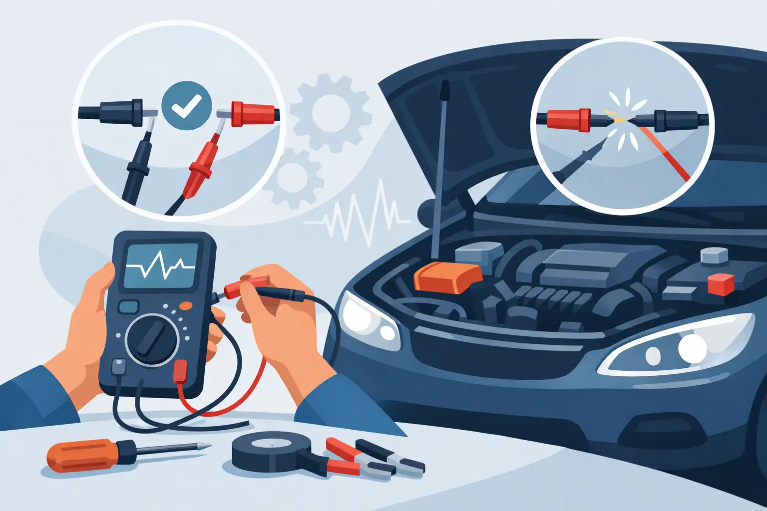
How to test wiring continuity with a multimeter
Set the meter correctly
Turn your multimeter to continuity mode if it has a beep function. If not, use the lowest ohms range or auto-ranging resistance mode. Touch the two leads together first. The meter should beep or show very low resistance, usually close to 0 ohms. That quick check confirms your leads and meter are working.
Identify the two test points
Use the wiring diagram to find the exact start and end of the wire. This could be from a fuse box terminal to a sensor connector, from a ground splice to a module pin, or between two harness connectors. Terminal position matters more than wire color alone, especially on repaired or aftermarket-modified harnesses.
Place one lead on each end of the wire
Touch one meter lead to the terminal at one end and the other lead to the matching terminal at the other end. If needed, use backprobe pins or terminal adapters rather than forcing oversized probes into the connector. Spread terminals once, and you can create a new intermittent problem.
Read the result
A good wire should show continuity with very low resistance. In a short automotive wire, that is often near 0 ohms, though lead resistance and connector contact can add a little. If the meter shows OL or no continuity, the wire is open somewhere between the test points.
If the reading jumps around, do not assume the wire is good. Move the harness by hand, especially near bends, door boots, hinge areas, battery trays, and previous repair points. A fluctuating reading while flexing the harness usually points to an internal break or poor terminal contact.
What counts as a good continuity reading
There is no single magic number for every vehicle, but for most point-to-point wire checks, you want resistance close to zero. A few tenths of an ohm can be normal depending on lead quality and connector condition. Several ohms on a simple wire run is suspicious, especially for sensor circuits, CAN lines, and low-voltage reference circuits where extra resistance can affect operation.
This is where context matters. A long harness run across a truck or SUV may read slightly higher than a short underhood jumper. Connector count also matters. Every terminal pair adds a little resistance. The key is consistency with the circuit design and the fault you are chasing.
Common mistakes when testing continuity
The biggest mistake is testing the circuit while it is still connected to modules or power sources. That can create false continuity through other components. Another common mistake is trusting the beep alone. Many meters beep at resistance levels that are too high for a sensitive automotive circuit to function correctly.
Testing through corrosion is another trap. Your probe may touch a contaminated terminal surface and give an unstable reading. If the connection looks discolored, loose, or heat-damaged, inspect it visually and test terminal tension if the circuit layout points in that direction.
The last major mistake is skipping the diagram. If you do not know where splices, intermediate connectors, or branch points are located, you can misread an open section as a full-wire failure. Good wiring data lets you divide the circuit in half and find the problem faster.
When continuity testing is not enough
A continuity result only tells part of the story. If a fuel pump feed, headlight circuit, blower motor power wire, or ground strap passes continuity but the component still underperforms, switch to a voltage drop test under load. That is the better way to catch high resistance caused by corrosion, partially broken strands, or overheated connectors.
This comes up often in older vehicles and in engine bay harnesses exposed to heat and oil. The wire may still beep out fine on the bench, but once the circuit carries current, the weak point shows up. If your symptoms include dim operation, slow motors, intermittent sensor codes, or module resets, do not stop at continuity.
A faster way to isolate an open wire
When a wire fails continuity and the harness is long, do not unwrap everything right away. Split the circuit into sections. Test from the first connector to the midpoint, then from midpoint to endpoint. Keep dividing until the open is confined to one section. This saves time and limits unnecessary harness damage.
On vehicles with multiple inline connectors, this method is especially effective. It also helps when the harness passes through common failure areas like firewall grommets, seat tracks, trunk lids, or door jambs. If you have exact connector views and splice locations, the process goes much faster.
Why wiring diagrams matter before you touch the meter
The better your circuit information, the fewer bad assumptions you make. A wire that looks like a simple straight run on the vehicle may pass through a junction connector, splice pack, ground distribution point, or control module. Without a proper diagram, you can test the wrong path and lose time on a circuit that was never the problem.
For shops and advanced DIY technicians, make-specific repair data is what turns continuity testing from guesswork into diagnostics. When you can see terminal numbers, connector locations, wire colors, and circuit routing before you start, you isolate opens faster and avoid damaging good parts. That is the difference between checking a wire and actually diagnosing the circuit.
If you are working across multiple brands, model years, and electrical architectures, having the correct documentation ready before you pick up the meter is usually the fastest part of the repair. AutoCarData is built around that need – buy and download the wiring information, verify the circuit layout, and start testing with the right pinout in front of you.
A continuity test is one of the fastest checks in electrical diagnostics, but only when you treat it as one step in a bigger process. Use it to confirm the path, isolate the section, and move on to loaded testing when the fault calls for it. The meter gives you the reading. The diagram tells you what it means.