Automotive Connector Identification Guide
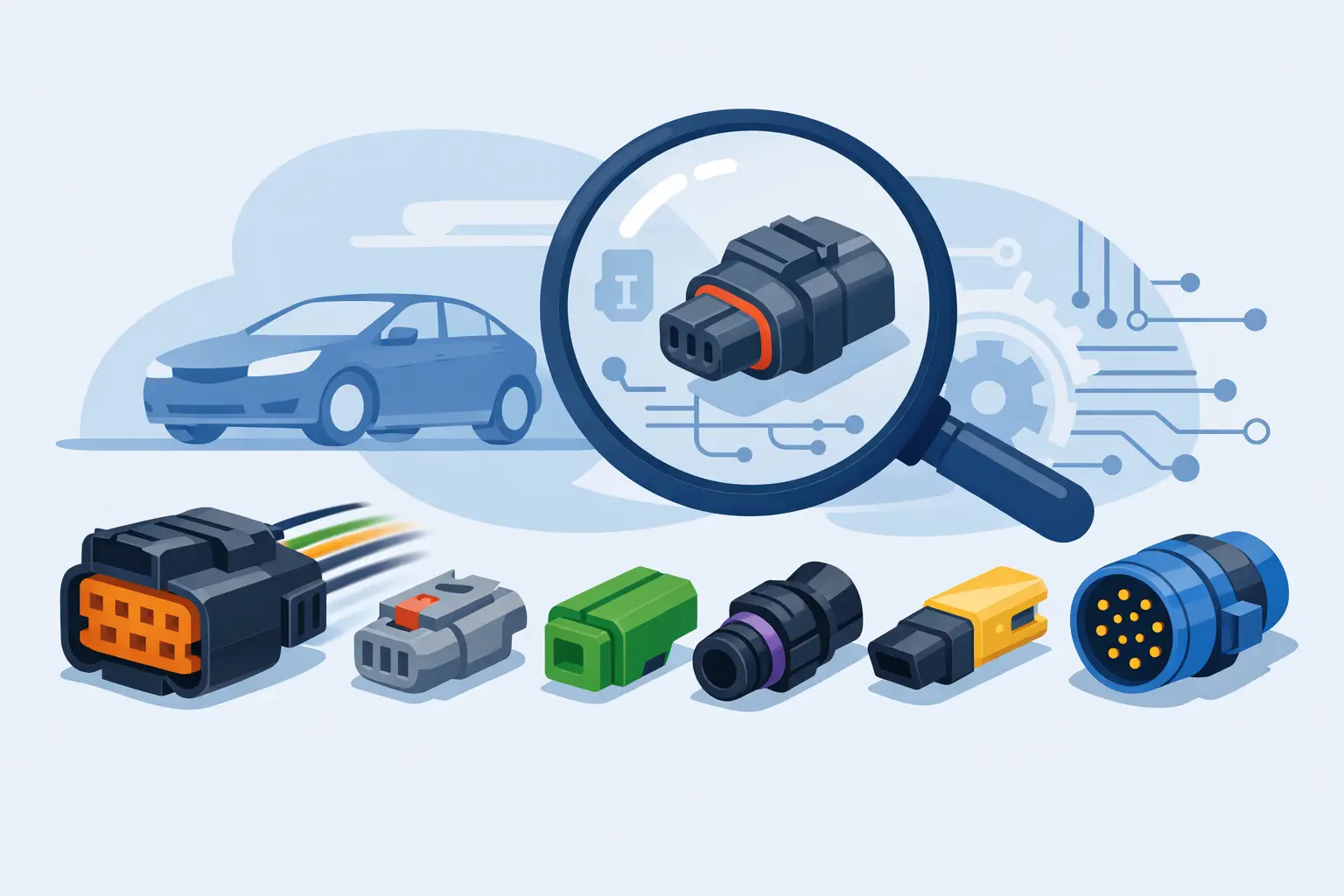
A bad connector call can waste an hour fast. You unplug one sensor, see a 2-pin housing that looks familiar, and order the wrong pigtail or test the wrong circuit. This automotive connector identification guide is built for techs and advanced DIY users who need to move from visual guesswork to confident identification.
Connector ID matters because modern vehicles reuse similar shapes across different systems, but the details that matter live in the small stuff. Pin count, keying, lock style, terminal size, seal color, and cavity layout all change what fits and what the connector actually does. If you are tracing an intermittent open, replacing a damaged plug, or confirming a wiring diagram callout, getting the connector right is part of getting the repair right.
What an automotive connector identification guide should help you confirm
A useful guide does more than show pictures of plugs. It should help you confirm three things: what family the connector belongs to, whether it matches the circuit shown in the wiring information, and whether the issue is the connector itself or the component attached to it.
That distinction matters in real jobs. A crank sensor connector and an EVAP solenoid connector may both look similar at a glance on some vehicles, especially when dirt, heat, and aftermarket repairs have changed the original appearance. If the connector shell shape gets most of your attention, you can still miss a mismatch in keyway position or terminal type.
The fastest way to identify a connector is to work from fixed features instead of general appearance. Start with the number of cavities. Then check whether all cavities are populated, because a 6-way shell may only carry 4 active circuits on a given trim level. After that, inspect the lock design, the face shape, the seal arrangement, and the indexing tabs that prevent wrong installation.
Start with connector family, not just the component
A common mistake is trying to identify the plug only by the part it connects to. That helps sometimes, but many vehicle platforms use the same connector family across sensors, actuators, lighting circuits, and chassis modules. The better approach is to identify the connector style first, then verify the circuit application.
Count cavities and note the layout
Cavity count is the first hard filter. Two-pin connectors are common, but there is a big difference between a flat side-by-side 2-way, a stacked 2-way, and an offset 2-way design. The cavity layout at the mating face often narrows the search faster than the wire colors do.
Wire colors help, but only to a point. Colors vary by make, model year, engine package, and previous repair work. Splices, replaced pigtails, and heat-damaged sections can make color-based identification unreliable. Use wire color as a secondary clue, not the deciding one.
Check keying and lock style
Connector keying is where many close-looking plugs stop being interchangeable. Look for ribs, slots, chamfered corners, molded guides, and polarizing tabs. Then inspect the secondary lock or terminal position assurance piece. On many connectors, that colored insert is just as important for identification as the main shell.
Lock style also matters for serviceability. Push-tab, lift-tab, slide-lock, and CPA-equipped connectors each point you toward specific families and failure patterns. A broken release tab may make a good connector look wrong if you are comparing it to a new replacement image, so account for damage before ruling it out.
Use terminal type and seal design to avoid wrong replacements
Two connectors can share the same cavity count and a similar housing shape but still use different terminals. That is where replacement jobs go sideways. If the housing accepts a different terminal width, tang style, or seal arrangement, a pigtail that looks close may not hold tension, weather-seal correctly, or lock into the body the way it should.
Sealed vs unsealed connectors
Sealed connectors are common in engine bay, underbody, and exterior locations. You will usually see individual wire seals, a perimeter seal, or both. Unsealed connectors are more common in interior and protected areas. This is not just a durability detail. It changes the housing depth, terminal retention, and mating dimensions.
If you are replacing a damaged connector, do not assume sealed and unsealed versions can substitute for each other just because the component side looks similar. Sometimes they can be adapted, but that becomes a harness repair decision, not a direct replacement. For production-style repairs, match the original design.
Terminal size and current load
Terminal size gives clues about circuit function. Small terminals often point to low-current signal circuits such as sensors or communication lines. Larger terminals are more common on motors, blower circuits, heated components, or power feeds. That does not identify the connector by itself, but it helps when the wiring diagram and physical connector need to agree.
If the shell says one thing and the expected current load says another, stop and verify. It may be the wrong connector, a previous splice repair, or a shared housing used with different terminal setups. This is where service information pays for itself.
Match the connector to the wiring diagram callout
Physical inspection gets you close. Wiring diagrams close the gap.
A proper diagram lets you confirm connector designation, cavity numbering, splice locations, ground references, and where the harness branches. That is what turns connector identification from a visual estimate into a diagnostic step. If you know the connector should be C123 with cavity 1 carrying a 5-volt reference and cavity 2 carrying sensor ground, you can verify both the plug and the circuit without guessing.
This is especially useful when multiple similar connectors sit in the same area. Front-end harnesses, transmission case connectors, ABS module plugs, and under-dash junction blocks often place look-alike connectors inches apart. The diagram tells you what should be present, where, and in what cavity order.
An inventory-based source for make-specific wiring documentation can save serious time here. Instead of hunting generic images and forum posts, you buy and download the exact diagrams for the vehicle in front of you and start the repair now.
Common connector identification problems in the bay
Heat and contamination change what you think you are looking at. Melted housings can distort the face shape. Oil intrusion can darken seals and hide lock colors. Road debris can break off indexing ribs that would normally identify the connector family.
Previous repairs create even more confusion. Aftermarket pigtails may use different wire colors. Butt connectors and heat shrink can shorten the harness and change how the connector sits in the bracket. On older vehicles, a replacement alternator or sensor may come with a revised connector design that requires a matching service pigtail.
That means connector identification is rarely just visual comparison. It is visual comparison plus circuit confirmation plus fitment logic.
A practical process for fast connector ID
When time matters, use the same sequence every time. Inspect the mating face and count cavities. Note the cavity pattern and whether every cavity is populated. Check for seals, lock style, CPA pieces, and keying features. Measure terminal size if needed. Then verify the connector designation and pinout against the wiring information for that exact vehicle.
This process sounds basic, but it prevents the most common waste: ordering by appearance alone. It also helps with diagnostics. If the connector is correct but terminal tension is weak, the problem is not identification anymore. It is connector condition.
When photos are enough and when they are not
Photos can get you close when the connector is clean, intact, and visible from the front and rear. They are less reliable when the connector is damaged, mounted in a tight location, or one of several near-identical variants used by the same manufacturer.
If the repair affects a critical circuit like ABS, airbag, transmission control, or CAN communication, do not rely on appearance alone. Pull the diagram, confirm the pinout, and verify cavity numbering before depinning or replacing anything.
Why vehicle-specific data changes the result
Generic connector charts are useful for training and rough sorting, but they do not replace vehicle-specific repair information. Automakers revise connector usage across trims, engines, emissions packages, and mid-year production changes. The same model line can have different harness layouts depending on build date and equipment.
That is why technicians who work efficiently do not stop at identifying the connector family. They confirm the connector in context of the actual vehicle. Make, model, year, engine, and system all matter. The documentation should match the car, not just the brand.
For shops handling multiple makes, fast access matters as much as accuracy. Waiting around for the right manual or digging through subscription menus slows the job. Downloadable wiring diagrams and chassis schematics let you move from connector question to repair decision with less dead time.
If connector problems are a regular part of your workload, build your process around exact documentation instead of memory. Connector families repeat, but the right answer still depends on the vehicle in your bay. Get the connector identified, get the circuit verified, and the repair gets a lot more straightforward from there.